A Practical Guide to TTL, CMOS and Universal Gate Logic
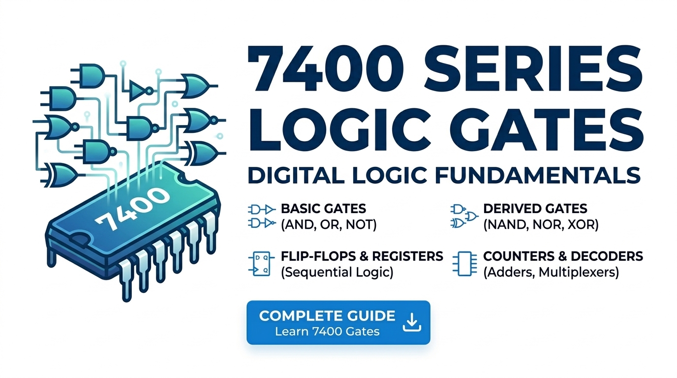
From the first 7400 NAND chip in 1964 to the 4093 Schmitt-trigger NAND still going strong today — what these families are, how they differ, and how to pick the right chip for your circuit.
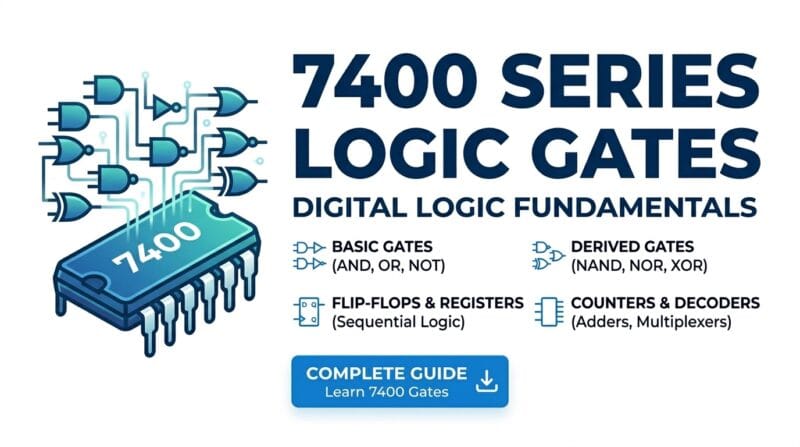
Table of Contents
Last updated: July 2026
🔴 What the 7400 Series Actually Is — and Why It Still Matters
This compatibility between manufacturers, combined with a fixed 5-volt supply requirement and predictable switching speeds, made the 7400 series the backbone of digital electronics through the 1970s and 1980s. Early microcomputers, calculators, and industrial controllers were built almost entirely from these chips. Today they appear in classrooms, hobby labs, and anywhere a quick prototype needs a reliable, cheap logic gate without the overhead of a microcontroller. A pack of 7408 AND gates from a local electronics shop costs a fraction of a dollar each and arrives in a familiar form that generations of textbooks have used as reference hardware.
The 7400 series started as a product line from Texas Instruments in 1964, built on Transistor-Transistor Logic (TTL) technology. The first chip in the family, the 7400, contained four 2-input NAND gates in a 14-pin ceramic package and cost several dollars each in 1964 money. The number scheme is simple: the middle digits describe the function (00 = quad 2-input NAND, 04 = hex inverter, 08 = quad 2-input AND) and everything is pinout-compatible across manufacturers. A 7408 from Texas Instruments and a 7408 from Fairchild Semiconductor will swap interchangeably on the same breadboard.
🟡 The 4000 Series: When Power Consumption Became the Problem

TTL has a fundamental weakness: it draws current even when it is doing nothing. The internal transistor arrangement means a TTL gate pulls meaningful static current from the supply rail at all times. That is fine when your circuit lives on a bench with a 1-amp linear regulator. It becomes a serious problem when you need the circuit to run for three months on four AA batteries.
The 4000 series, built on Complementary Metal-Oxide-Semiconductor (CMOS) technology, solved this. RCA introduced the first 4000-series chips in 1968. A CMOS gate draws current only when switching — during the brief moment when the output transitions from high to low or low to high. Between transitions, current consumption is in the nanoamp range. As described in the Wikipedia overview of 4000-series ICs, these chips also accept a much wider supply voltage: 3V to 15V, compared to TTL’s fixed 5V window. That flexibility makes CMOS the natural choice for circuits running from coin cells, solar cells, USB power, or anything battery-operated.
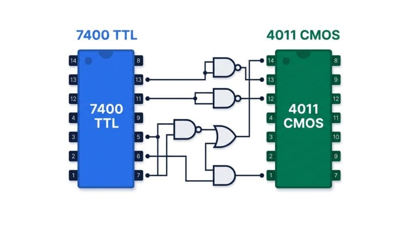
The 4000-series part number maps to the same logic functions as the 7400 family. The 4011 is a quad 2-input NAND (matching the 7400), the 4081 is a quad 2-input AND (matching the 7408), the 4071 is a quad 2-input OR (matching the 7432). The functions are identical; only the technology and voltage range change. You can explore all 35 ICs across both families — with gate count, input count, package type, and supply voltage — in the Digital Logic Studio Pro IC Library tab.
🟢 TTL vs CMOS: The Numbers That Matter
Three parameters determine which family belongs in your circuit:
- 🔵 Supply voltage. TTL: 4.75V–5.25V (5V ±5% — no exceptions). CMOS: 3V–15V. If your supply varies or runs below 5V, CMOS is the only option.
- 🟠 Static current draw. A single TTL gate draws around 1–2mA idle. A CMOS gate in the same configuration draws under 1µA — roughly 2,000 times less. Multiply by 20 chips in a circuit and the battery life difference is dramatic.
- 🟣 Switching speed. Standard 7400 TTL gates switch in 10–22 nanoseconds. Standard 4000 CMOS at 5V is slower, around 60–125 nanoseconds. High-speed CMOS families (74HC, 74HCT) close this gap to under 10ns, but those are separate product lines rather than the classic 4000 series.
One rule that trips up beginners: never leave a CMOS input pin floating. An unconnected CMOS input will drift to whatever voltage the surrounding environment imposes on it — this makes the gate’s output unpredictable and can cause the chip to oscillate and heat up. Tie unused CMOS inputs to GND (for NAND, NOT) or VCC (for NOR, AND) through a 10kΩ resistor to give them a defined logic level.
🔴 Why NAND and NOR Are Called Universal Gates
Any Boolean function can be implemented using only NAND gates, or only NOR gates. This is not a coincidence — it is a mathematical property of Boolean algebra, and it has a direct practical consequence for hardware design.
Here are the three most useful NAND-only constructions:
- 🔵 NOT from NAND: Wire both inputs of a 2-input NAND to the same signal. NAND(A, A) = NOT A. One gate, one connection.
- 🟠 AND from NAND: NAND(A, B), then NAND the output with itself. Two gates total — one less efficient than a real AND gate, but it only requires the 7400 chip.
- 🟣 OR from NAND: NAND each input with itself (getting NOT A and NOT B), then NAND those two results. Three NAND gates reproduce an OR function exactly — verifiable by De Morgan’s theorem: NAND(NOT A, NOT B) = NOT(NOT A AND NOT B) = A OR B.
The real-world reason this matters: if you are prototyping a circuit that needs AND, OR, and NOT gates but only have 7400 NAND chips on your bench, you can build the entire circuit without ordering anything else. This is exactly the kind of conversion the Digital Logic Studio Pro Analyzer tab generates automatically — type your expression, see both the NAND-only and NOR-only forms, and wire accordingly. According to the Wikipedia article on Boolean algebra, the universality of NAND was formally proved by Henry Sheffer in 1913, decades before the first transistor was built.
🟡 Matching Your Expression to the Right Chip
The gate type tells you which part number to look for, but the input count determines which variant to pick. Most beginners default to the 2-input quad packages (7400, 7408, 7432) without realizing that 3-input and 4-input variants exist and can save board space significantly.
For a 3-input AND function in TTL: the 7411 gives you three independent 3-input AND gates in one package. Without it, you would need to cascade two 7408 gates — wasting a gate, adding a propagation delay, and using more of the chip. For a 4-input NAND: the 7420 (dual 4-input NAND) handles it cleanly. For an 8-input NAND — common in address decoders — the single 7430 puts a full 8-input NAND gate in one 14-pin package. Knowing these variants exist is what separates a clean schematic from one that wastes chips.
To minimize the expression before selecting a chip, run it through the Boolean Expression Simplifier to see step-by-step law reductions, or use the K-Map Solver Pro for 2-to-5 variable Karnaugh map minimization. Both tools cross-link back to the Digital Logic Studio Pro so the full IC-to-chip workflow stays in one browser session.
🟢 Three ICs Worth Knowing Beyond the Basics
4093 — Schmitt-Trigger NAND (CMOS): A standard NAND switches sharply at a single threshold voltage. The 4093 adds hysteresis — the threshold for a rising input (high going) is higher than for a falling input (low going). This noise immunity is essential when the input signal is slow, noisy, or comes from a button or capacitor. Bouncy mechanical switches wired directly to a standard logic gate cause multiple spurious output pulses; the same switch through a 4093 produces a clean single transition.
4049 — Hex Inverter/Buffer (CMOS, 16-pin): Unlike the 4069 (standard hex inverter), the 4049 is rated to accept inputs above its supply voltage, making it the standard choice for level shifting — for example, converting 12V logic signals down to 5V for a microcontroller. The extra two pins (versus 14-pin) give it a separate high-supply input for the input side of the level shift.
7430 — Single 8-input NAND (TTL): Eight inputs, one output, 14-pin DIP. In a classic 8-bit address decoder, the 7430 detects when all eight address lines are in a specific pattern simultaneously — without it, you would need four 2-input NAND gates cascaded in two levels. One chip, one gate delay, one line on the schematic. It is a niche part, but when you need it, nothing else competes.
Can I mix a 7408 AND gate with a 4071 OR gate in the same circuit?
Technically yes, but the output of the 4071 (CMOS) at 15V will destroy the 7408 (TTL) input rated for 5V. If you run both chips at 5V and keep signal voltages within 0–5V, the combination works in practice. A dedicated level-shifting buffer (like the 4049) between families is the safer approach.
Why is CMOS used in nearly all modern chips when TTL came first?
Power consumption. A CMOS transistor pair only draws current during switching, whereas bipolar TTL transistors draw current continuously. As chips scaled from hundreds to billions of transistors, CMOS’s near-zero static current became the only viable option. Every smartphone processor, FPGA, and memory chip today uses CMOS at its core.
What does it mean that NAND is a universal gate?
It means any Boolean function — and therefore any digital circuit — can be built using only NAND gates. AND, OR, NOT, XOR, and every combination of them can be reproduced from NAND alone. This is mathematically provable using De Morgan’s theorems. NOR is also universal by the same logic applied to the dual form.
How do I convert a Boolean expression to NAND gates manually?
Apply double negation to each AND-OR term: NOT(NOT(A AND B)) stays logically the same but gives you a NAND inside a NOT. Then use the NAND-as-NOT trick on the outer NOT. It is error-prone by hand for anything beyond two terms — the Digital Logic Studio Pro does the full conversion automatically using recursive De Morgan’s theorem application.
What is propagation delay and why does it matter?
Propagation delay is the time between an input changing and the output responding. Standard 7400 TTL: 10–22ns. Standard 4000 CMOS at 5V: 60–125ns. In a cascaded circuit with five gate levels, worst-case delay is the sum of each stage. At high clock speeds this delay sets the maximum operating frequency. For slow sensor circuits it is irrelevant; for high-speed counters it defines the design limit.
What is the 74HC series and how does it relate to the 7400 series?
74HC (High-speed CMOS) is a later family that uses CMOS technology but adds pinout compatibility with the 7400 TTL series and matches or beats TTL switching speeds. A 74HC08 runs on 2V–6V, draws CMOS-level current, and switches in under 10ns — the best of both worlds. It is a different product line from the classic 4000 series but uses the same 74xx numbering as TTL.
How do I verify my Boolean simplification before wiring anything?
Three tools cover this on this site. Run the original and simplified expressions side by side in the Truth Table Studio Pro Equivalence tab — it flags every row where they disagree. Use the K-Map Solver Pro for visual minimization. Use the Boolean Expression Simplifier for step-by-step law application.
Is the 4000 series still manufactured or is it obsolete?
Still actively manufactured. The 4011, 4013, 4017, 4040, and 4093 in particular remain in continuous production by Texas Instruments, ON Semiconductor, and others. They appear in industrial control circuits, audio electronics, and educational kits worldwide. Pricing remains low — typically under $0.30 per chip in single quantities.