Boolean Minimization Explained: Quine–McCluskey, Prime Implicants & Gate Cost
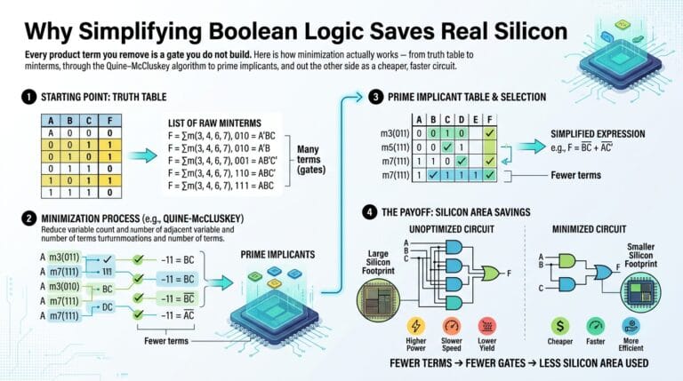
Why Simplifying Boolean Logic Saves Real Silicon Every product term you remove is...
Boolean algebra is one of the few subjects where the theory and the tool are genuinely the same thing. That makes this category the most technical on the site.
The posts work through the actual algorithms. How Quine–McCluskey finds prime implicants and why it beats a Karnaugh map the moment you pass four variables, where visual grouping stops being reliable. Why NAND and NOR are functionally complete, and what that means when you are staring at a chip that only has one gate type on it. How a truth table becomes a canonical SOP form, and how that form becomes synthesisable Verilog.
Written for undergraduates in a digital-logic course, self-taught FPGA hobbyists, and teachers building problem sets. The worked examples use real expressions with real intermediate steps, not a clean textbook case chosen because it happens to come out neatly.
Read the method here, then run the same expression through the Boolean Algebra Studio and check that its answer matches the one you derived by hand. If it does not, one of you is wrong — and finding out which is the whole exercise.
Why Simplifying Boolean Logic Saves Real Silicon Every product term you remove is...

Why Simplifying Boolean Logic Saves Real Silicon Every product term you remove is a gate you do not build. Here is how minimization actually works — from truth table to minterms, through the Quine–McCluskey algorithm to prime implicants, and out the other side as a cheaper, faster circuit. Last updated: July 2026 🔴 What minimization is … Read more

There Is No Number 42 Inside a Computer Only ever a pattern of...
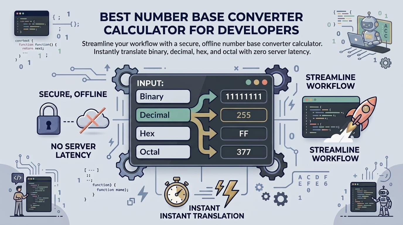
There Is No Number 42 Inside a Computer Only ever a pattern of on and off. Every base conversion, every negative sign, every decimal point is a convention layered on top of that one physical fact. Here is how those conventions were built, and why each one is shaped the way it is. Last updated: … Read more

How Truth Tables Really Work A truth table looks like homework busywork until...
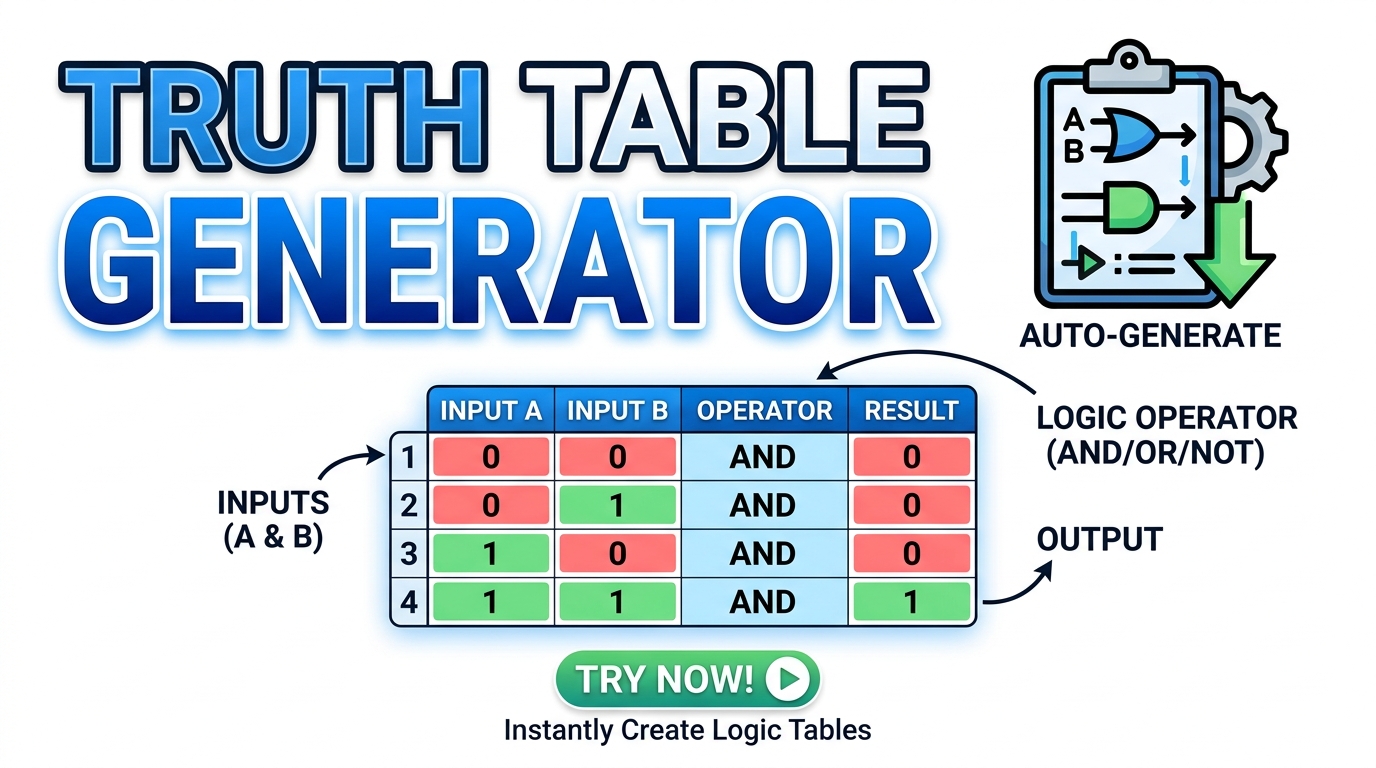
How Truth Tables Really Work A truth table looks like homework busywork until you notice what it is: the complete, unambiguous specification of a circuit. Every minterm, every Karnaugh map, every NAND-only implementation and every satisfiability question starts from that grid of ones and zeros. Here is the theory underneath it. Last updated: July 2026 … Read more
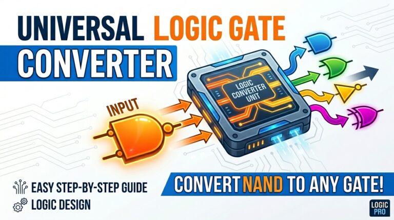
Best Universal Logic Gate Converter: Simplify Digital Design Convert Boolean expressions to NAND/NOR,...

Best Universal Logic Gate Converter: Simplify Digital Design Convert Boolean expressions to NAND/NOR, generate Verilog & VHDL, build truth tables, K-Maps, and analyze gate count — 100% offline. Related Article Slug: universal-logic-gate-converter-guide Last updated: June 2026 🔴 The Foundational Mathematics of Digital Hardware Designing digital circuits can be incredibly mathematically intensive without the correct methodologies … Read more
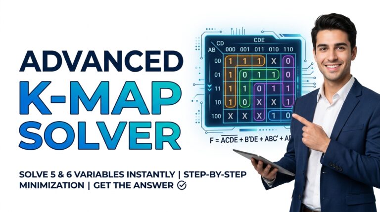
Karnaugh Map Guide — Grouping Rules, Quine-McCluskey Algorithm Simplify complex digital logic instantly....
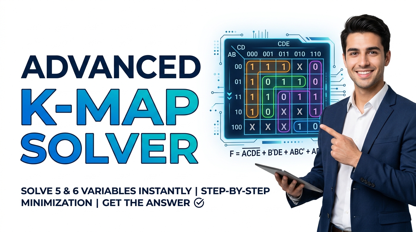
Karnaugh Map Guide — Grouping Rules, Quine-McCluskey Algorithm Simplify complex digital logic instantly. Discover how an advanced k-map solver optimizes Boolean algebra equations offline with maximum privacy.. Last updated: June 2026 🔴 Why Boolean Minimization Matters — Gates, Literals, and Circuit Cost Every additional gate in a digital circuit adds propagation delay, increases silicon area, … Read more

A Practical Guide to TTL, CMOS and Universal Gate Logic From the first...
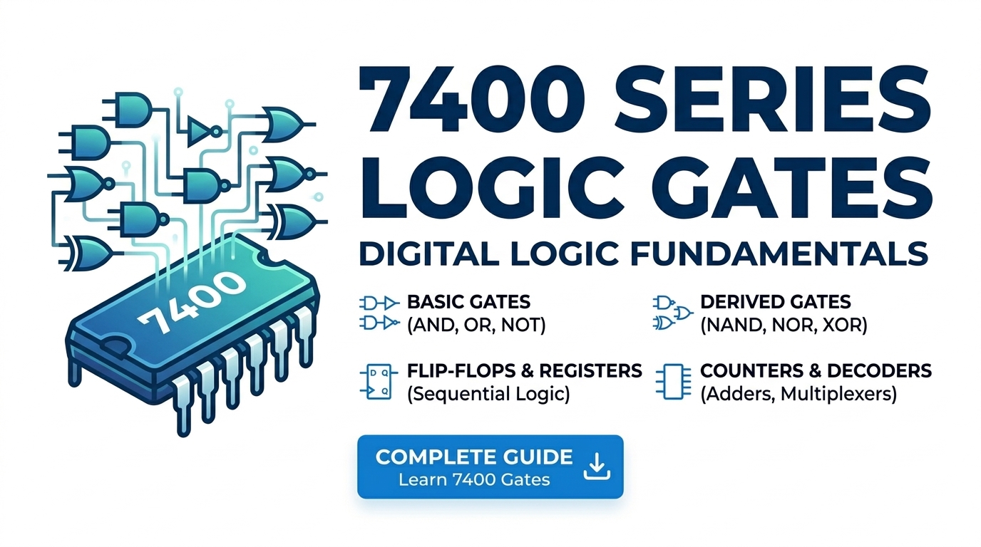
A Practical Guide to TTL, CMOS and Universal Gate Logic From the first 7400 NAND chip in 1964 to the 4093 Schmitt-trigger NAND still going strong today — what these families are, how they differ, and how to pick the right chip for your circuit. Last updated: July 2026 🔴 What the 7400 Series Actually Is … Read more