
Karnaugh Map Guide — Grouping Rules, Quine-McCluskey Algorithm
Simplify complex digital logic instantly. Discover how an advanced k-map solver optimizes Boolean algebra equations offline with maximum privacy..

Table of Contents
Last updated: June 2026
🔴 Why Boolean Minimization Matters — Gates, Literals, and Circuit Cost
Every additional gate in a digital circuit adds propagation delay, increases silicon area, and consumes more power. A function implemented with six AND gates and three OR gates costs more in every measurable dimension than the same function implemented with two AND gates and one OR gate. Boolean minimization directly determines gate count through two metrics: the number of product terms (which determines how many AND gates are needed) and the number of literals (which determines how many AND gate inputs are needed). A literal is a variable in either complemented or uncomplemented form — A is one literal, A' is also one literal. Minimizing both simultaneously is the core goal of K-Map and Quine-McCluskey minimization.
For small circuits — 2 to 4 variables — the savings from minimization are modest in absolute terms but significant in relative terms. A canonical 4-variable SOP with 8 minterms requires 8 four-input AND gates and one 8-input OR gate — 32 literal connections. The same function might minimize to two 2-literal terms, requiring only 2 two-input AND gates and one 2-input OR gate — 4 literal connections, an 87.5% reduction. In programmable logic devices (FPGAs, CPLDs), minimization determines how many lookup tables (LUTs) are consumed, which directly limits how many other functions can share the same device.
🟡 Constructing a Karnaugh Map — Variable Assignment and Gray Code Ordering
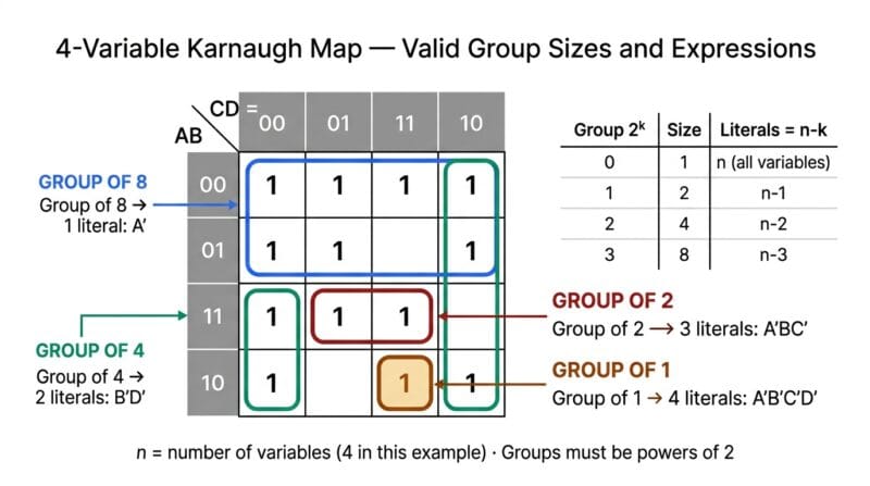
A Karnaugh map is a two-dimensional grid representing all possible input combinations for an n-variable Boolean function. For n variables, the map has 2ⁿ cells — 4 cells for 2 variables, 8 for 3, 16 for 4, 32 for 5, 64 for 6. The row and column labels use Gray code — a sequence where adjacent entries differ in exactly one bit. For two bits, the sequence is 00, 01, 11, 10 (not binary 00, 01, 10, 11). This ordering ensures that physically adjacent cells in the map correspond to logically adjacent minterms — minterms that differ in exactly one variable. The ability to group adjacent cells depends entirely on this property.
For a 4-variable K-Map, variables A and B label the rows and variables C and D label the columns. The rows are ordered AB = 00, 01, 11, 10 and the columns are ordered CD = 00, 01, 11, 10. Cell (row AB=01, column CD=11) contains minterm number 7 (binary 0111, decimal 7). To read which minterm occupies a cell, concatenate the row label with the column label — the resulting binary number is the minterm index. For a 5-variable map, the standard approach splits variables into two groups of 2 and 3, creating two side-by-side 4×4 maps — one for the first variable at 0 and one at 1. For 6 variables, four 4×4 maps are arranged in a 2×2 layout with the first two variables labeling which map to read.
🟢 Identifying Groups — Valid Sizes, Wrap-Around, and Covering Priority
The fundamental rule of K-Map grouping is that groups must be rectangular collections of 1, 2, 4, 8, 16, or 32 cells — always powers of 2. Groups of any other size are not valid. The group must contain only cells with F=1 or F=X (don’t care) — cells with F=0 may never be included. The map wraps around on all edges: the leftmost column is adjacent to the rightmost column, and the top row is adjacent to the bottom row. In a 4-variable map, this means the four corners together form a valid group of 4 even though they are not physically adjacent in the printed layout.
Covering strategy follows a greedy principle — always form the largest possible groups first. A single uncovered 1-cell forms a group of 1 covering all n variables. Pairing it with one adjacent 1-cell forms a group of 2 eliminating one variable. Finding four mutually adjacent 1-cells (forming a square or rectangle) creates a group of 4 eliminating two variables. The goal is to cover all 1-cells using the minimum number of the largest possible groups. Every 1-cell must appear in at least one group — a 1-cell may appear in multiple groups if doing so allows other cells to form larger groups. Don’t care cells should be included in groups whenever they allow a group to be larger, but don’t care cells that cannot contribute to any group are simply ignored and contribute nothing to the expression.
🟢 Quine-McCluskey — The Algorithmic Version of K-Map Minimization
The Quine-McCluskey algorithm produces the same result as a correctly drawn K-Map but operates through mechanical comparison rather than visual pattern recognition. Given a set of minterms (and don’t cares), the algorithm first groups them by their number of 1-bits (Hamming weight). Within adjacent groups, it compares every pair of terms looking for pairs that differ in exactly one bit position. When found, the differing bit is replaced with a dash and the merged term is added to the next iteration. Terms that cannot be merged with any other term in the current iteration are prime implicants — they cannot be absorbed into a larger grouping.
The prime implicant chart maps which prime implicants cover which minterms. Essential prime implicants — those that are the only prime implicant covering some minterm — must appear in the final expression. After selecting all essential prime implicants, the chart is simplified and the remaining uncovered minterms are covered through additional prime implicant selection. When multiple prime implicants cover remaining minterms with equal efficiency, Petrick’s Method resolves the ambiguity by enumerating all valid covers. This distinction matters for circuit optimization: in a CMOS implementation, two equally minimal expressions might have very different wire routing costs or timing paths through the combinational logic cone.
🟡 SOP and POS Duality — When to Minimize 0s Instead of 1s
Sum of Products (SOP) minimization groups the 1-cells of the K-Map. Product of Sums (POS) minimization groups the 0-cells. Both represent the same Boolean function — they are dual representations of the same truth table. The choice between SOP and POS depends on which form produces the simpler expression, which in turn depends on whether the function has more 1-cells or 0-cells. A function with 12 minterms and 4 maxterms will almost always produce a simpler POS expression than SOP, because there are fewer 0-cells to cover and they may group more efficiently.
The SOP form maps directly to an AND-OR two-level gate structure: one AND gate per product term, whose outputs feed a single OR gate. The POS form maps to an OR-AND two-level structure: one OR gate per sum term, whose outputs feed a single AND gate. Both are two-level implementations with identical propagation delay paths (ignoring different fan-in). In practice, digital synthesis tools explore both forms and select the one that maps better to the target technology’s cell library — the choice is made automatically rather than manually for ASIC and FPGA design. For student work and manual circuit design, checking both SOP and POS and comparing the literal counts is the correct approach to finding the most economical implementation. Use our Digital Logic Studio Pro to toggle between SOP and POS with one click and compare the resulting expressions. For more Boolean algebra reference visit our K-Map complete guide.
🟢 From Boolean Expression to HDL — The Operator Translation
Each HDL language has its own notation for the three fundamental Boolean operations. In Verilog and SystemVerilog, AND is written with &, OR with |, and NOT with ~. An expression like AB' + CD becomes A & ~B | C & D in Verilog. Operator precedence in Verilog matches standard Boolean algebra — NOT binds tighter than AND, which binds tighter than OR — so parentheses are only required when the intended grouping differs from this default. In VHDL, the operators are English words: and, or, not, xor. Unlike Verilog, VHDL does not define precedence among and, or, and not beyond not having standard precedence — parentheses are therefore required when mixing and and or in VHDL to avoid ambiguity.
The assign statement in Verilog creates a continuous assignment — the hardware equivalent of a wire whose value continuously reflects the right-hand expression. Any time an input signal changes, the output updates combinatorially with only the inherent gate propagation delay. SystemVerilog’s always_comb block is the behavioral description of the same hardware — it executes whenever any signal in the sensitivity list changes, and the synthesizer infers what combinational logic implements the behavior. In C, the Boolean logic operators && (AND), || (OR), and ! (NOT) operate on values and return 0 or 1, making them appropriate for simulating logic functions in software — the bitwise operators &, |, and ~ would also work for single-bit operands but differ in behavior for multi-bit values.
- 🔵 Essential prime implicants must always appear in the final minimized expression — they cover minterms that no other prime implicant covers. Removing an essential PI leaves at least one minterm uncovered, making the expression incorrect.
- 🟠 Redundant prime implicants are PIs whose minterms are already fully covered by other selected PIs. They are never included in the minimal expression — including them would add terms without adding coverage, strictly increasing the expression size.
- 🟣 XOR-based minimization (ESOP — Exclusive Sum of Products) is a third form not covered by standard K-Maps that can sometimes produce even shorter expressions when the function has significant XOR structure. Functions like parity generators and Gray code converters are natural XOR functions that SOP/POS representations describe poorly.
What is the difference between a minterm and a maxterm?
A minterm is a product term (AND of literals) that evaluates to 1 for exactly one row of the truth table — each variable appears exactly once, either complemented (if the variable is 0 in that row) or uncomplemented (if 1). Minterm m₅ for 4 variables is A’BC’D (binary 0101). A maxterm is a sum term (OR of literals) that evaluates to 0 for exactly one row — each variable appears once, complemented if it is 1 in that row and uncomplemented if 0. Maxterm M₅ is (A + B’ + C + D’). The canonical SOP is the OR of all minterms where F=1; the canonical POS is the AND of all maxterms where F=0. They represent the same function by duality.
Why does my K-Map give a different answer than the textbook?
Several reasons can cause legitimate differences. First, multiple equally minimal solutions may exist — if Petrick’s Method shows multiple solutions with the same literal count, either is correct. Second, SOP/POS mode matters — ensure you and the textbook are both minimizing the same form. Third, don’t care handling differs: this tool includes don’t care cells in groups that benefit from them, which may produce a different expression than a textbook that makes different don’t care assignments. Fourth, variable ordering in K-Maps can vary between textbooks — some place AB on rows, others on columns, which changes cell positions without affecting the logical result. The minimized expression should produce the same truth table regardless of which correct method produced it.
What does the step-by-step trace show?
The trace shows four steps: Step 1 lists the minterms and don’t care indices being processed. Step 2 lists all prime implicants found by Quine-McCluskey — shown as binary strings where a dash (-) indicates a don’t care position in the implicant (a cancelled variable). Step 3 identifies which prime implicants were selected as essential or added by the greedy/Petrick cover algorithm. Step 4 shows the final minimized expression. This trace is particularly useful for coursework verification — compare each step against your manual working to identify exactly where a discrepancy occurs.
How are corners handled in a 4-variable K-Map?
In a 4-variable K-Map, the four corner cells (minterms 0, 2, 8, 10) are all mutually adjacent through wrap-around: the left edge wraps to the right edge and the top edge wraps to the bottom edge. All four corners have AB=00 or AB=10 (so A can be 0 or 1) and CD=00 or CD=10 (so C can be 1 or 0). They form a valid group of 4 covering the term B’D’ — both B and D are 0 in all four corners. This wrap-around adjacency is the most commonly missed grouping opportunity in manual K-Map exercises, so the solver’s colour-coded display specifically helps identify these non-obvious groups.
What is Petrick’s Method and when should I use it over greedy?
Petrick’s Method is an exact algorithm for finding all prime implicant covers of minimum cost. It builds a Boolean function P whose satisfying assignments are valid covers, then expands P into sum of products form — each product term is a valid cover and the minimum-length terms are the minimal covers. Use Petrick’s Method when: you need to verify there is only one minimal solution, when the greedy result seems larger than expected, when comparing your manual solution against a computed one for coursework, or when the implementation technology has preferences between equivalent expressions. For speed in interactive use, greedy solves in milliseconds; Petrick’s is slower on large problems with many prime implicants.
Can I use the VHDL output in Xilinx ISE or other older EDA tools?
Yes. The generated VHDL follows IEEE 1076 standard syntax (VHDL-93 compatible) using only the basic STD_LOGIC data type and fundamental logic operators. This is compatible with Xilinx ISE, Xilinx Vivado, Intel Quartus Prime, ModelSim, GHDL, and any IEEE-compliant VHDL simulator or synthesizer. The only library required is IEEE.STD_LOGIC_1164, which is the universal standard VHDL library available in all tools. Save the output as a .vhd file, create a new project, add the file as a source, and run synthesis — no modifications should be needed for a standard combinational logic function.
What is the relationship between K-Map groups and the number of literals in each term?
The relationship is direct and consistent: a group of 2ᵏ cells in an n-variable K-Map produces a product term with exactly n−k literals. For a 4-variable map (n=4): a group of 1 cell (k=0) gives a 4-literal term — every variable appears. A group of 2 cells (k=1) gives a 3-literal term. A group of 4 cells (k=2) gives a 2-literal term. A group of 8 cells (k=3) gives a 1-literal term — only one variable is constant across all 8 cells. A group of 16 cells (k=4) covering the entire map gives the constant 1, requiring no literals at all. This relationship explains why maximizing group size directly minimizes literal count and gate input count.
What is the difference between assign in Verilog and always_comb in SystemVerilog?
Both describe combinational logic but with different styles. assign is a continuous assignment — an explicit declarative statement that wire F equals the expression. It is always active and updates instantly when any input changes. always_comb is a procedural block — it executes like a process in software, triggered whenever any signal in its sensitivity list changes. In always_comb, you write statements procedurally (F = expression;) inside the block. The synthesizer infers from the behavior what combinational circuit to build. For simple single-expression combinational logic, assign is more concise. For complex conditional logic with multiple outputs, always_comb is cleaner. Both produce identical synthesized hardware for combinational functions.
How do I handle a Boolean function that is always 0 or always 1?
A function with all 0s (no minterms) is the constant 0 function — the Verilog assign F = 1'b0;, VHDL F <= '0';, Python return False. A function with all 1s is the constant 1 — assign F = 1'b1;, F <= '1';, return True. The K-Map solver detects both cases and returns the appropriate constant expression before attempting any minimization. In real circuits, a constant 0 output is simply connected to ground (VSS) and a constant 1 output to supply (VDD) — no logic gates are needed. The HDL generator handles both cases correctly in all five output formats.